Sices ATS (Automatic Transfer Switch)
- Sices ATS (Automatic Transfer Switch) panel is designed for the management of the switch between two sources:
- One Mains and one stand-by genset;
- One Mains and group of stand-by gensets;
- Two gensets
- Two Mains
- I.e. the ATS panel comprises all the circuits, devices and controls which enable the switch between the mains and the genset, in order to supply the load in case of mains failure.
- The ATS panel is made with a steel sheet subjected to a painting treatment using high resistance epoxy powder and the power circuit is safety separated from the control area in accordance to the main operation rules.
- The protection degree with opened door is IP20.
- With closed door. The standard protection degree is IP54 or IP55 (for the ATS LOGICA depending on the dimensions).
- Related to the power circuit of the ATS, several solutions are available based on the Customer’s need.
- The operating voltage is 400/230V (± 10%).
- Frequency 50/60Hz
- Battery voltage: 12Vdc up to 125A & 24Vdc (available upon request)
- 12/24Vdc from 160A
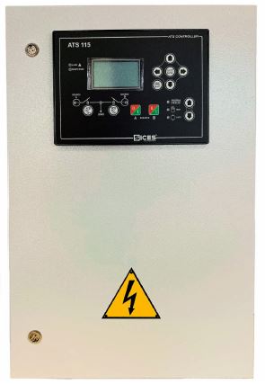
MAIN FEATURES OF THE ATS CONTROL PANEL
- Microprocessor based controller ATS115 (in case of ATS LOGICA only).
- Couple of mechanical end electric interlocked contactors with aux. contacts or motorized changeover switch with aux. contacts included.
- Power cable connection of the front.
- Incoming and Outgoing cable from the bottom (if not different specified)
- Epoxy powder treatment colour RAL7035
- External protection degree with closed door
LOGICA VERSION IP54/55
- Internal degree with opened door IP20.
- Temperature operation of the devices fit into the control panel £40 °C.
- The indicated power (kVA) is the maximum that can be used according to the power circuit capacity (A); it does not consider emergency service operation.
- Operating voltage 230/400V (±10%) – 50/60Hz.
- Special multi voltage version available. Please clarify it before the order.
- Different and customized enquiries not comprised into the follow prices tables must be addressed to the sales Office.
Conformity to the following rules
- 2006/95/CE – LOW VOLTAGE DIRECTIVE
- 2004/108/CE – EMC DIRECTIVE
- 93/68/CEE – CE STAMP REGULATION
- CEI EN 61439-1/2 – LOW VOLTAGE CONTROL PANEL DIRECTIVE
GENERAL NOTES
- (*) Amps are calculated assuming an input voltage of 400V.
- In case of different voltages, please calculate the Amps based on the power of the genset.
- From 45A to 125A the power circuit is composed by a couple of electrical and interlocked contactors. The accepted supply voltage range is 100 – 250V.
- Cables incoming and outgoing from the BOTTOM.
- Protection degree:
- LOGICA Version ≤ 400 IP55
- LOGICA Version ≥ 630A IP54
- Installation and start-up activities are not included.